


Computerized cable connectors tensile testing machine as per IEC61238-1
Computerized cable connectors tensile testing machine as per IEC61238-1
1.introductions
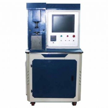
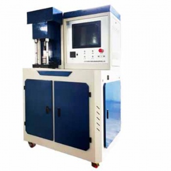
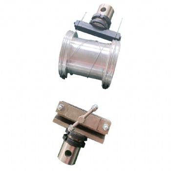
The computerized cable connectors tensile testing machine can be used to measure and determine the mechanical strength for connectors to the conductors of power cables, such as buried cables or cable installed in building. The test grips of universal tensile testing machine can be designed according to shape of cable termination to suitable for connectors with different size and shape. Software of universal tensile testing machine can display force in real time. Test results can be saved and printed after test.
2. relative manufacturing and calibrating test method for testing machine
GB/T2611 general requirements for testing machines
GB/T16491 electronic universal testing machine
GB/T16825.1 verification of static uniaxial testing machines --- part 1: tension / compression testing machines --- verification and calibration of the force measuring system
ISO7500-1 metallic materials--- verification of static uniaxial testing machine --- part 1: tension / compression testing machines --- verification and calibration of the force measuring system
ASTM E4 standard practice for force verification of testing machines
EN 10002-2 tensile testing of metallic materials --- part 2: verification of the force measuring system of the tensile testing machine
3. relative test method for tensile strength test of compression and mechanical connectors for power cables
GB/T 9327 compression and mechanical connectors for power cables for rated voltages up to 35KV (Um=40.5KV) --- test methods and requirements
IEC 61238-1 compression and mechanical connectors for power cables ---
part 1-1: test methods and requirements for compression and mechanical
connectors for power cables for rated voltages up to 1KV (Um=1.2KW)
tested on non-insulated conductors
4. specification of testing machine

china computerized cable connectors tensile testing machine as per IEC61238-1 real time graph generation during test multi-language software for UTM UTM training and support services safety protocols for universal testing machines price factory supplier
How to Select the Right Tensile, Compression, Bending, Shear, Peel, and Tear Testing Machine: Calculation Formulas with Examples
Selecting the appropriate testing machine for tensile, compression, bending, shear, peel, and tear tests requires careful consideration of multiple factors, including the force range, specimen dimensions, test standards, and machine capabilities. Below are the key calculation formulas to help determine the necessary machine specifications, along with examples for better understanding.
1. Tensile Testing Machine Selection
Tensile testing machines measure the maximum tensile strength and elongation of materials.
Key Formula:
Fmax=σmax × A
Where:
Fmax = Maximum required force (N)
σmax = Ultimate tensile strength of the material (MPa)
A = Cross-sectional area of the specimen (mm²)
Example: For a steel specimen with σmax =400MPa and cross-sectional area A =100mm²:
Fmax=400 × 100=40,000N (40kN)
A 50 kN tensile testing machine would be suitable.
2. Compression Testing Machine Selection
Compression tests determine a material's resistance to compressive forces.
Key Formula:
Fmax=σc × A
Where:
Fmax = Maximum required force (N)
σc = Compressive strength of the material (MPa)
A = Cross-sectional area of the specimen (mm²)
Example: For a concrete cube with σc =30MPa and A =1502=22,500mm²:
Fmax=30 × 22,500=675,000N (675kN)
A 1000 kN compression testing machine would be ideal.
3. Bending Testing Machine Selection
Bending tests evaluate the flexural strength of materials.
Key Formula for Three-Point Bending:

Where:
σf = Flexural stress (MPa)
F= Applied force (N)
L= Span length (mm)
b= Width of the specimen (mm)
h= Thickness of the specimen (mm)
Example: For a wooden beam with L=500mm, b=50mm, h=25mm, and requiring a stress of 10 MPa:

A 5 kN bending tester would be suitable.
4. Shear Testing Machine Selection
Shear tests determine the shear strength of materials.
Key Formula:
Fmax=τ × A
Where:
Fmax = Maximum shear force (N)
τ= Shear strength of the material (MPa)
A = Shear area (mm²)
Example: For an aluminum sheet with τ=90 MPa and A=200mm²:
Fmax=90×200=18,000N(18kN)
A 20 kN shear testing machine is recommended.
5. Peel Testing Machine Selection
Peel tests measure the adhesion strength between bonded materials.
Key Formula:

Where:
P= Peel strength (N/mm)
F= Measured force (N)
W= Width of the specimen (mm)
Example: For a tape with F=50N and W=25mm:

A peel testing machine with at least 5 N force capacity is required.
6. Tear Testing Machine Selection
Tear tests determine the resistance of a material to tearing forces.
Key Formula:

Where:
Ftear= Tear strength (N/mm)
F= Measured force (N)
t= Thickness of the specimen (mm)
Example: For a rubber sheet with F=100N and t=2mm:

A tear testing machine with 100 N capacity is needed.
When selecting a testing machine, ensure that the maximum force capacity of the machine is at least 1.2 to 1.5 times the calculated force to account for safety margins and unexpected variations. Additionally, consider compliance with relevant test standards (ASTM, ISO, GB, EN, JIS) and machine features such as speed control, data acquisition, and test automation.
By using the above formulas and examples, engineers and manufacturers can accurately determine the appropriate testing machine specifications for their specific material and application requirements.


Categories
- electronic universal testing machine
- hydraulic universal testing machine
- impact testing machine
- compression testing machine
- horizontal tensile testing machine
- manhole cover testing machine
- pellet compression testing machine
- material testing machine
- steel strand tensile testing machine
- rubber testing equipment
- plastic testing equipment
- load cell
- Böhme abrasion tester
- all testing machine and equipment
- ceramic tiles testing equipment
- asphalt mixture testing equipment
- footwear testing machine
- test fixtures
- torsion tester
- cupping testing machine
- friction and wear tester
Hot Products
Contact Us
- +86-18615632092
- sophie@jnwtbte.com
- +86-18615632092
 Send Email
 售前客服
售前客服