


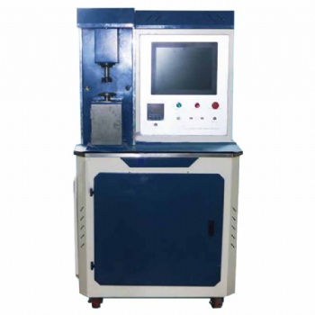
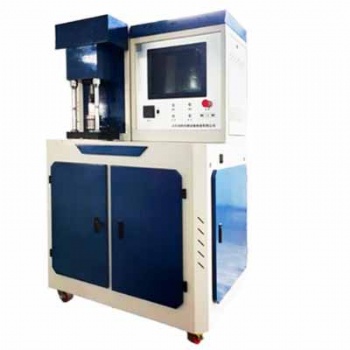
Computerized glass cover Bending Tester
Computerized glass cover Bending Tester
1 Introduction
Microcomputer-controlled glass cover bending testing machine can be used to test the three-point bending strength and four-point bending strength of materials such as mobile phone cover, tablet computer, liquid crystal glass, touch glass, photovoltaic glass and plastic. The microcomputer-controlled glass cover bending testing machine system adopts microcomputer closed-loop control, has a wide and accurate loading speed and force measurement range, and has high precision and sensitivity for the measurement and control of load and displacement.
2.relative test method for glass cover bending test
JJG/T676 test method for flexure of glass material
JC/T 2130 cover glass for windows of mobile electronic devices
GB/T 9341 plastics – determination of flexural properties
ISO 178 plastics – determination of flexural properties
BS EN 1288-3 determination of bending strength of glass – part 3: test with specimen supported at two points ( four point bending)
GB/T 1449 fibre-reinforced plastic composites – determination of flexural properties
ISO 14125 fibre-reinforced plastic composites – determination of flexural properties
ASTM D6109 standard test method for flexural properties of unreinforced and reinforced plastic lumber and related products
3. Relative manufacturing and calibrating test method for cover glass bending testing machine
GB/T2611 general requirements for testing machines
GB/T16491 electronic universal testing machine
GB/T16825.1 verification of static uniaxial testing machines --- part 1: tension / compression testing machines --- verification and calibration of the force measuring system
ISO7500-1 metallic materials--- verification of static uniaxial testing machine --- part 1: tension / compression testing machines --- verification and calibration of the force measuring system
ASTM E4 standard practice for force verification of testing machines
EN 10002-2 tensile testing of metallic materials --- part 2: verification of the force measuring system of the tensile testing machine
4. working conditions of testing machine
4.1 The room temperature is 10-35℃.
4.2 Relative humidity≤80%.
4.3 There is no vibration around, no corrosive medium, and no strong magnetic field interference.
4.4 The power supply voltage fluctuation should not exceed 10% of the rated voltage.
4.5 Install it horizontally on a solid foundation with a level of 0.2/1000.
5. features of test software
5.1. Automatic stop: After the sample is broken, the moving beam stops automatically;
5.2. Condition storage: The test control data and sample conditions can be made into modules, which facilitates the batch test;
5.3. Automatic speed change: The speed of the moving beam during the test can be changed automatically according to the preset program or manually;
5.4. Automatic calibration: the system can automatically realize the calibration of the indication accuracy;
5.5. Automatic save: After the test is over, the test data and curves are automatically saved;
5.6. Process realization: the test process, measurement, display and analysis are all completed by the microcomputer;
5.7. Batch test: for samples with the same parameters, it can be completed in sequence after one setting
5.8. Test software: WINDOWS interface, menu prompt, mouse operation;
5.9. Display mode: data and curves are dynamically displayed with the test process;
5.10. Curve traversal: After the test is completed, the curve can be re-analyzed, and the test data corresponding to any point on the curve can be found with the mouse;
5.11. Curve selection: Stress-strain, force-displacement, force-time, displacement-time and other curves can be selected for display and printing as required;
12. Test report: The report can be prepared and printed according to the format required by the user;
5.13. Limit protection: with two levels of program control and mechanical limit protection;
5.14. Overload protection: when the load exceeds 3-5% of the maximum value of each gear, it will automatically stop;
5.15. The test results are obtained in two modes, automatic and manual, and reports are automatically formed, which makes the data analysis process simple.
6. specification of cover glass bending testing machine
No | Item | Specification |
1 | Force capacity | 100N,200N,500N,1000N,2000N,5000N |
2 | Force measuring range | 0.4%-100%FS |
3 | Error of force value | Less than ±1% of set value |
4 | Resolution of test force | 1/500000 |
5 | Displacement resolution | 0.0025mm |
6 | Accuracy of elongation measuring | ±0.5% |
7 | Crossbeam speed range | 0.05-500mm/min |
8 | Precision of displacement speed control | ±1%(0.01-10mm/min); ±0.5%(10-500mm/min) |
9 | Accuracy of constant force, constant displacement, displacement elongation control | When set value is less than 10%FS,error is less than ±1.0% of set value When set value is more than 10%FS,error is less than ±0.1% of set value |
10 | Accuracy of deformation control | When set value is less than 0.05%FS,error is less than ±2.0% of set value When set value is more than 0.05%FS,error is less than ±0.5% of set value |
11 | Distance between tensile grips | 650mm |
12 | Voltage | Single phase,220V±10%,50Hz |
13 | Dimension | 520x480x1550mm |
14 | Weight | 80kg |
china 100n 200n 500n 1000n 2000n 5000n corrosion testing with computerized glass cover bending tensile environmental chamber tester universal testing machine UTM for aerospace alloys nanomaterials and thin films thermal testing price factory supplier
How to Select the Right Tensile, Compression, Bending, Shear, Peel, and Tear Testing Machine: Calculation Formulas with Examples
Selecting the appropriate testing machine for tensile, compression, bending, shear, peel, and tear tests requires careful consideration of multiple factors, including the force range, specimen dimensions, test standards, and machine capabilities. Below are the key calculation formulas to help determine the necessary machine specifications, along with examples for better understanding.
1. Tensile Testing Machine Selection
Tensile testing machines measure the maximum tensile strength and elongation of materials.
Key Formula:
Fmax=σmax × A
Where:
Fmax = Maximum required force (N)
σmax = Ultimate tensile strength of the material (MPa)
A = Cross-sectional area of the specimen (mm²)
Example: For a steel specimen with σmax =400MPa and cross-sectional area A =100mm²:
Fmax=400 × 100=40,000N (40kN)
A 50 kN tensile testing machine would be suitable.
2. Compression Testing Machine Selection
Compression tests determine a material's resistance to compressive forces.
Key Formula:
Fmax=σc × A
Where:
Fmax = Maximum required force (N)
σc = Compressive strength of the material (MPa)
A = Cross-sectional area of the specimen (mm²)
Example: For a concrete cube with σc =30MPa and A =1502=22,500mm²:
Fmax=30 × 22,500=675,000N (675kN)
A 1000 kN compression testing machine would be ideal.
3. Bending Testing Machine Selection
Bending tests evaluate the flexural strength of materials.
Key Formula for Three-Point Bending:

Where:
σf = Flexural stress (MPa)
F= Applied force (N)
L= Span length (mm)
b= Width of the specimen (mm)
h= Thickness of the specimen (mm)
Example: For a wooden beam with L=500mm, b=50mm, h=25mm, and requiring a stress of 10 MPa:

A 5 kN bending tester would be suitable.
4. Shear Testing Machine Selection
Shear tests determine the shear strength of materials.
Key Formula:
Fmax=τ × A
Where:
Fmax = Maximum shear force (N)
τ= Shear strength of the material (MPa)
A = Shear area (mm²)
Example: For an aluminum sheet with τ=90 MPa and A=200mm²:
Fmax=90×200=18,000N(18kN)
A 20 kN shear testing machine is recommended.
5. Peel Testing Machine Selection
Peel tests measure the adhesion strength between bonded materials.
Key Formula:

Where:
P= Peel strength (N/mm)
F= Measured force (N)
W= Width of the specimen (mm)
Example: For a tape with F=50N and W=25mm:

A peel testing machine with at least 5 N force capacity is required.
6. Tear Testing Machine Selection
Tear tests determine the resistance of a material to tearing forces.
Key Formula:

Where:
Ftear= Tear strength (N/mm)
F= Measured force (N)
t= Thickness of the specimen (mm)
Example: For a rubber sheet with F=100N and t=2mm:

A tear testing machine with 100 N capacity is needed.
When selecting a testing machine, ensure that the maximum force capacity of the machine is at least 1.2 to 1.5 times the calculated force to account for safety margins and unexpected variations. Additionally, consider compliance with relevant test standards (ASTM, ISO, GB, EN, JIS) and machine features such as speed control, data acquisition, and test automation.
By using the above formulas and examples, engineers and manufacturers can accurately determine the appropriate testing machine specifications for their specific material and application requirements.


Categories
- electronic universal testing machine
- hydraulic universal testing machine
- impact testing machine
- compression testing machine
- horizontal tensile testing machine
- manhole cover testing machine
- pellet compression testing machine
- material testing machine
- steel strand tensile testing machine
- rubber testing equipment
- plastic testing equipment
- load cell
- Böhme abrasion tester
- all testing machine and equipment
- ceramic tiles testing equipment
- asphalt mixture testing equipment
- footwear testing machine
- test fixtures
- torsion tester
- cupping testing machine
- friction and wear tester
Hot Products
Contact Us
- +86-18615632092
- sophie@jnwtbte.com
- +86-18615632092
 Send Email
 售前客服
售前客服