
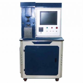
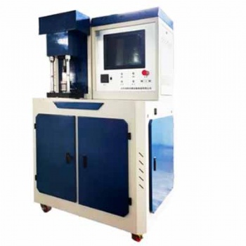
Computerized wire tensile tester for dense woven wire cloth GB/T 21648
![]() single column tension tester.jpg
single column tension tester.jpg
1. brief introductions
The computerized wire tensile tester can be used to determine and measure tensile properties including max. breaking force, elongation, yield point, elastic modulus, etc. of wires used on dense woven wire cloth in room temperature.
Test software of the tensile testing machine can display force / load, test time, displacement, deformation and test curves in real time during test. And after test, the software can save test parameters and test curves for later enquiry and allow print test report when connect to a printer.
The wire tensile tester allows equipping with other test grips for tension, compression, bending, shear, peeling for other metal and non-metal materials.
2. relative test methods
GB/T228.1 metallic materials---tensile testing---part 1:method of test at ambient temperature
ISO 6892-1 metallic materials---tensile testing---part 1:method of test at room temperature
GB/T 21648 industrial dense woven wire cloth
GB/T 16825.1 / ISO 7500-1 metallic materials --- calibration and verification of static uniaxial testing machines---part 1: tension/ compression testing machines – calibration and verification of the force-measuring system
3. specifications
No. | Item | Spec. |
1 | Force capacity | 100N,200N,500N,1KN,2KN,5KN |
2 | Effective force measuring range | 0.4%-100%FS |
3 | Relative error of force measuring | ±0.5% |
4 | Force resolution | 1/500000 |
5 | Displacement measuring resolution | 0.001mm |
6 | Relative error of displacement | ±0.5% |
7 | Relative error of deformation | ±0.5% |
8 | Test speed range | 0.05-500mm/min |
9 | Relative error of displacement speed | ±0.5% |
10 | Relative error of stress( force) speed | ±1.0% |
11 | Relative error of stress (force) keep | ±1.0% |
12 | Relative error of strain (deformation) speed | ±1.0% |
13 | Relative error of strain (deformation) keep | ±1.0% |
14 | Data collecting speed | 15 times /s |
15 | Distance between grips | 650mm max. |
16 | Compress plate hardness | 55HRC |
17 | Voltage | Single phase,220V±10%,50Hz |
18 | Dimension | 520x480x1550mm |
19 | Weight | 80kg |
4. features of testing machine
4.1 attractive appearances, convenient and easy to operate, stable and reliance performance, no pollution, low noise.
4.2 The main loading frame has high and 700mm test space suitable for most test samples. The main loading frame is convenient to install test samples, test accessories.
4.3 By using AC servo system in the main loading frame, the control accuracy of the machine is improved and machine works very stable during test. Displacement test speed range is from 0.05mm/min to 500mm/min, suitable for most metal and non-metal materials and can adjust the test space quickly.
4.4 it can equip with different load cells to meet with test requirement for different test samples.
4.5 closed-loop control of stress, strain and displacement. Different control mode can switch freely without impact. Test force, peak force value, displacement, test speed, test status, test curve can be displayed in real time during test.
4.6 it has the functions of maintaining or keep certain test force, displacement, deformation for certain period and auto return to original place after test sample is broken.
4.7 protecting functions of over load, over current, over voltage.
5. working conditions
5.1. Room temperature 10-35 ℃.
5.2. Relative humidity ≤ 80%.
5.3. There is no vibration, corrosive media, or strong magnetic field interference around.
5.4. The fluctuation of power supply voltage shall not exceed 10% of the rated voltage.
5.5. Install horizontally on a stable foundation with a levelness of 0.2/1000.
6. test software
6.1 main interface

Software main interface components:
A. Title Block: display area of software name and currently used test scheme name;
B. Menu bar: software system parameter setting area;
C. Toolbar: common function button operation area of software;
D. Display bar: software real-time numerical display area;
E. Curve bar: display area where software draws real-time curve;
F. Data column: display area of test parameters, results and control steps;
G. Control bar: control button area to control machine loading / unloading;
H. Status bar: area displaying basic operation status of software.
5.2 many test method and allow add new test method by client


5.3 different test curves can be put together for comparing

5.4 different control mode, displacement control, load control, self-edited test steps control

How to Select the Right Tensile, Compression, Bending, Shear, Peel, and Tear Testing Machine: Calculation Formulas with Examples
Selecting the appropriate testing machine for tensile, compression, bending, shear, peel, and tear tests requires careful consideration of multiple factors, including the force range, specimen dimensions, test standards, and machine capabilities. Below are the key calculation formulas to help determine the necessary machine specifications, along with examples for better understanding.
1. Tensile Testing Machine Selection
Tensile testing machines measure the maximum tensile strength and elongation of materials.
Key Formula:
Fmax=σmax × A
Where:
Fmax = Maximum required force (N)
σmax = Ultimate tensile strength of the material (MPa)
A = Cross-sectional area of the specimen (mm²)
Example: For a steel specimen with σmax =400MPa and cross-sectional area A =100mm²:
Fmax=400 × 100=40,000N (40kN)
A 50 kN tensile testing machine would be suitable.
2. Compression Testing Machine Selection
Compression tests determine a material's resistance to compressive forces.
Key Formula:
Fmax=σc × A
Where:
Fmax = Maximum required force (N)
σc = Compressive strength of the material (MPa)
A = Cross-sectional area of the specimen (mm²)
Example: For a concrete cube with σc =30MPa and A =1502=22,500mm²:
Fmax=30 × 22,500=675,000N (675kN)
A 1000 kN compression testing machine would be ideal.
3. Bending Testing Machine Selection
Bending tests evaluate the flexural strength of materials.
Key Formula for Three-Point Bending:

Where:
σf = Flexural stress (MPa)
F= Applied force (N)
L= Span length (mm)
b= Width of the specimen (mm)
h= Thickness of the specimen (mm)
Example: For a wooden beam with L=500mm, b=50mm, h=25mm, and requiring a stress of 10 MPa:

A 5 kN bending tester would be suitable.
4. Shear Testing Machine Selection
Shear tests determine the shear strength of materials.
Key Formula:
Fmax=τ × A
Where:
Fmax = Maximum shear force (N)
τ= Shear strength of the material (MPa)
A = Shear area (mm²)
Example: For an aluminum sheet with τ=90 MPa and A=200mm²:
Fmax=90×200=18,000N(18kN)
A 20 kN shear testing machine is recommended.
5. Peel Testing Machine Selection
Peel tests measure the adhesion strength between bonded materials.
Key Formula:

Where:
P= Peel strength (N/mm)
F= Measured force (N)
W= Width of the specimen (mm)
Example: For a tape with F=50N and W=25mm:

A peel testing machine with at least 5 N force capacity is required.
6. Tear Testing Machine Selection
Tear tests determine the resistance of a material to tearing forces.
Key Formula:

Where:
Ftear= Tear strength (N/mm)
F= Measured force (N)
t= Thickness of the specimen (mm)
Example: For a rubber sheet with F=100N and t=2mm:

A tear testing machine with 100 N capacity is needed.
When selecting a testing machine, ensure that the maximum force capacity of the machine is at least 1.2 to 1.5 times the calculated force to account for safety margins and unexpected variations. Additionally, consider compliance with relevant test standards (ASTM, ISO, GB, EN, JIS) and machine features such as speed control, data acquisition, and test automation.
By using the above formulas and examples, engineers and manufacturers can accurately determine the appropriate testing machine specifications for their specific material and application requirements.


Categories
- electronic universal testing machine
- hydraulic universal testing machine
- impact testing machine
- compression testing machine
- horizontal tensile testing machine
- manhole cover testing machine
- pellet compression testing machine
- material testing machine
- steel strand tensile testing machine
- rubber testing equipment
- plastic testing equipment
- load cell
- Böhme abrasion tester
- all testing machine and equipment
- ceramic tiles testing equipment
- asphalt mixture testing equipment
- footwear testing machine
- test fixtures
- torsion tester
- cupping testing machine
- friction and wear tester
Hot Products
Contact Us
- +86-18615632092
- sophie@jnwtbte.com
- +86-18615632092
 Send Email
 售前客服
售前客服