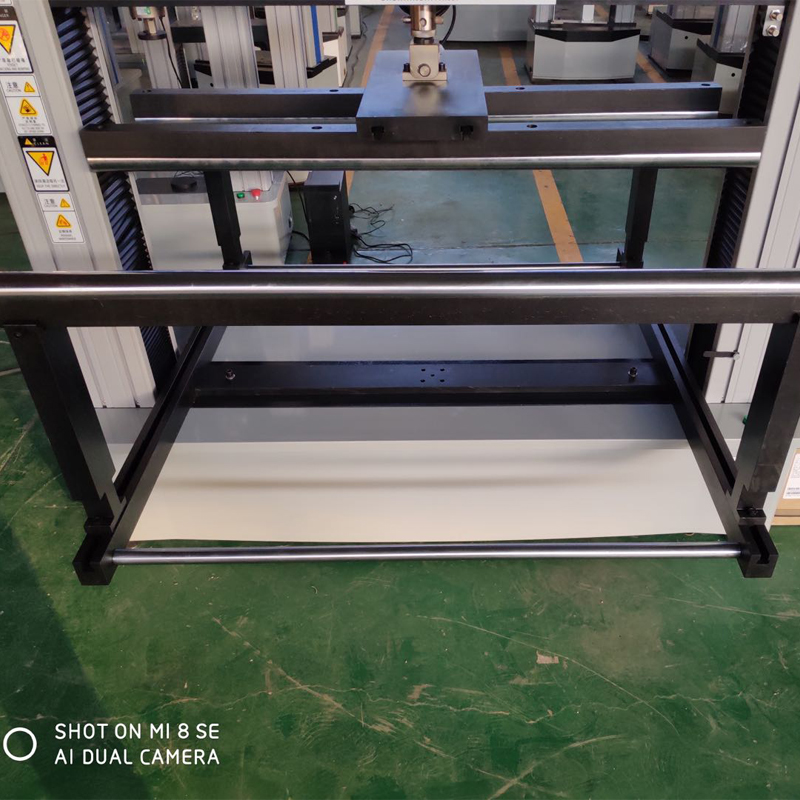
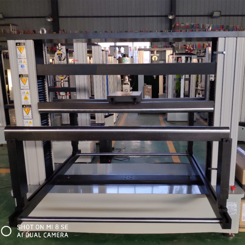
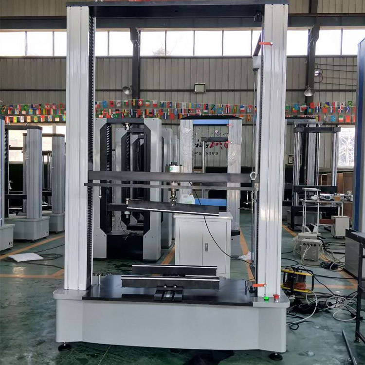
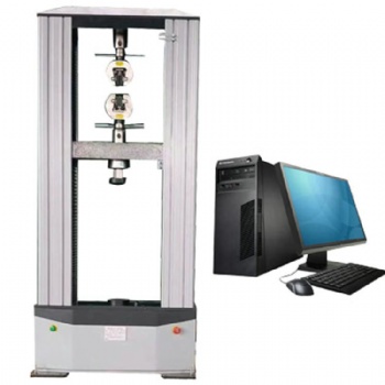
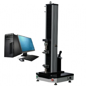
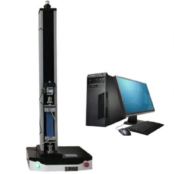
Computerized glass three and four point flexural testing machine
The computer-controlled three-point and four-point bending test machine can test the bending strength of glass by three-point bending and four-point bending test methods
Computerized glass three and four point flexural testing machine
1. introductions
The computer-controlled three-point and four-point bending test machine can test the bending strength of glass by three-point bending and four-point bending test methods, that is, under the specified test conditions, a sample of a certain size and shape is subjected to three-point static bending or four-point static bending load, the bending strength of the specimen is obtained by calculating the bending stress at the cross-section under the load. The microcomputer-controlled three-point and four-point bending testing machine can test the bending strength of tempered glass for construction, photovoltaic glass and glass materials for mobile phones according to different force values and different bending test attachments.
2. relative test method of glass bending and flexural test
GB/T 17841 heat strengthened glass
GB/T 34328 light weight thermally strengthened glass
EN 1288-3 glass in building – determination of bending strength of glass --- part 3: test with specimen supported at two points (four point bending)
JC/T 676 test method for flexure of glass material
GB 15763.4 safety glazing materials in building --- part 4: heat soaked thermally tempered glass
EN 14179-1 glass in building – heat soaked thermally toughened soda lime silicate safety glass --- part 1: definition and description
3. Relative manufacturing and calibrating test method for testing machine
GB/T2611 general requirements for testing machines
GB/T16491 electronic universal testing machine
GB/T16825.1 verification of static uniaxial testing machines --- part 1: tension / compression testing machines --- verification and calibration of the force measuring system
ISO7500-1 metallic materials--- verification of static uniaxial testing machine --- part 1: tension / compression testing machines --- verification and calibration of the force measuring system
ASTM E4 standard practice for force verification of testing machines
EN 10002-2 tensile testing of metallic materials --- part 2: verification of the force measuring system of the tensile testing machine
4. working conditions of testing machine
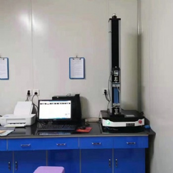
4.1 The room temperature is 10-35℃.
4.2 Relative humidity≤80%.
4.3 There is no vibration around, no corrosive medium, and no strong magnetic field interference.
4.4 The power supply voltage fluctuation should not exceed 10% of the rated voltage.
4.5 Install it horizontally on a solid foundation with a level of 0.2/1000.
5. features of test software
5.1. Automatic stop: After the sample is broken, the moving beam stops automatically;
5.2. Condition storage: The test control data and sample conditions can be made into modules, which facilitates the batch test;
5.3. Automatic speed change: The speed of the moving beam during the test can be changed automatically according to the preset program or manually;
5.4. Automatic calibration: the system can automatically realize the calibration of the indication accuracy;
5.5. Automatic save: After the test is over, the test data and curves are automatically saved;
5.6. Process realization: the test process, measurement, display and analysis are all completed by the microcomputer;
5.7. Batch test: for samples with the same parameters, it can be completed in sequence after one setting
5.8. Test software: WINDOWS interface, menu prompt, mouse operation;
5.9. Display mode: data and curves are dynamically displayed with the test process;
5.10. Curve traversal: After the test is completed, the curve can be re-analyzed, and the test data corresponding to any point on the curve can be found with the mouse;
5.11. Curve selection: Stress-strain, force-displacement, force-time, displacement-time and other curves can be selected for display and printing as required;
12. Test report: The report can be prepared and printed according to the format required by the user;
5.13. Limit protection: with two levels of program control and mechanical limit protection;
5.14. Overload protection: when the load exceeds 3-5% of the maximum value of each gear, it will automatically stop;
5.15. The test results are obtained in two modes, automatic and manual, and reports are automatically formed, which makes the data analysis process simple.
Categories
- electronic universal testing machine
- hydraulic universal testing machine
- impact testing machine
- compression testing machine
- horizontal tensile testing machine
- manhole cover testing machine
- pellet compression testing machine
- material testing machine
- steel strand tensile testing machine
- rubber testing equipment
- plastic testing equipment
- load cell
- Böhme abrasion tester
- utm
- ceramic tiles testing equipment
- asphalt mixture testing equipment
- footwear testing machine
Contact Us
- +86-18615632092
- wtbequipment@hotmail.com
- sophie-tester
- +86-18615632092


 售前客服
售前客服